Smart Water Dispenser
by: Tomás Ospina.
🔗 View on GitHub — sensor-interface PCB
Overview
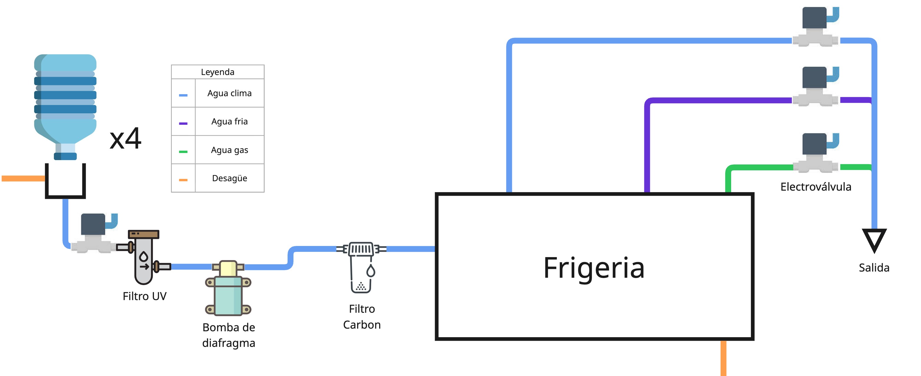
This project transforms a basic water dispenser into an intelligent machine that measures its available water in real time, enabling predictive refills before the tank ever runs dry. Beyond monitoring, I designed the full water-automation process and a wireless maintenance interface, so technicians can service the unit remotely.
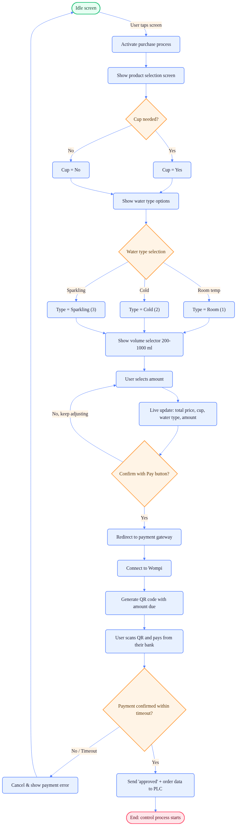
A Raspberry Pi 4 acts as the central hub linking the user, the PLC, and the online payment module, while a custom Qt interface handles all on-screen interaction. I also redesigned and modeled the system’s power panel — adding fuses and control relays to guard against overloads — and cut the machine’s manufacturing cost by replacing the original controller with a commercial PLC better matched to the system’s requirements.
IoT Integration
For continuous monitoring, I installed sensors on both the water inlet and the dispensing outlet. The machine’s status is published over the internet using the MQTT protocol, giving a live view of its state. A planned next step is to add emergency alerts that report faults and help prevent malfunctions before they occur.
Remote Maintenance Access
A machine-locking system restricts access to authorized technicians for periodic servicing. Using VNC, a technician connects to the PLC’s visual interface over the internet — releasing the locks directly from the PLC without any specialized equipment. The entire process runs from the technician’s phone, secured by unique credentials over the system’s Wi-Fi network.
PLC ↔ Raspberry Pi Communication
The PLC and Raspberry Pi communicate over MODBUS TCP. A Python program captures the variables a user generates on screen and forwards them to the PLC module, keeping the two controllers in sync.
The two flow charts below map the system’s logic — the control-side state machine and the user-facing interaction flow:

Current Work
I am currently designing a PCB that interfaces the flow sensors — which operate at 5 V — with the PLC’s digital inputs, which operate at 24 V. The 3D model below shows the sensor-interface module; drag to rotate it:
Technologies
- Python (MODBUS TCP client, data handling)
- Commercial PLC
- Raspberry Pi 4
- MQTT (IoT telemetry)
- VNC (remote maintenance)
- Qt (user interface)
- KiCad (power panel & sensor-interface PCB)